These are the threaded holes provided by Humber for the gearbox mounting.
The location tolerance is fairly "loose" which probably explains why the stock cross member has oversize holes and uses big washers with the mounting bolts
The location tolerance is fairly "loose" which probably explains why the stock cross member has oversize holes and uses big washers with the mounting bolts
This shows part of the chassis construction that fouled the desired mount point on the LHS. I adjusted it slightly with a precision adjusting tool. i.e. belted it with the 2 lb hammer :-)
Drawing Mark 1
Thought I might need to brace the mounts back to a cross piece further back to get sufficient strength but it was not needed.
First revision showing the Triton cross member and the adjustment to the relative positions of vehicle mount points and the gearbox mount
Using the Humber mount to check the rear mounting points
Using the Humber mount to check the front mounting points
OK this one shows the driveshaft that was conveniently exactly the correct length after I adjusted the engine position to clear the LH steering arm.
A question for Humber experts is why is there a big space in the driveshaft tunnel on the left side of the driveshaft?
Driveshaft area looking forwards
The mounted Triton cross member in place
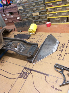
A string of pictures showing the construction of the adaptor brackets made to allow the use of the stock Triton cross member and rubbers.
LHS trial fit, Humber holes all over the place :-)
LHS and cross member trial fit
LHS from front
LHS second trial fit
LHS bolted up complete ready for paint
Steering clearance around bell housing
RHS looking back Humber brake and fuel lines
RHS looking forwards
Brake and fuel lines this side
From Right side
Well there is one task completed and the gearbox mounted where I needed it.
I also unbolted the front engine mounts to release the tension on the rear I mentioned in a previous post. and had to drill the RHS mount 11 mm forward to allow the engine to sit correctly with the rear of the gearbox now central and the front offset about 40 mm to the left. Other wise I could see early failure of the rubber mounts.
This shows the re-drilled mount on the RHS.
This allowed that side of the engine to sit 11 mm further back.When it is all pulled out to paint the engine bay I will widen the engine mount pad to be fully supported by the mount rubber and add a bit to the brace.
The front of the engine is now sitting freely in this position with no levering needed to slip the bolts into the front cross member.
LHS front engine mount. I slotted the holes in the little support tower which let this side be slightly lower than the first mounting position and this gives about 5 mm more clearance this side for exhaust pipes.
It is that snug in there :-)
Next post will be the oil filter adaptor that needed an 11th hour redesign to ensure sufficient seal around the oil holes for a reliable oil seal. Can't be losing oil pressure when it is all together and running because of cutting corners in the early stages.


No comments:
Post a Comment